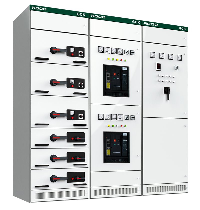
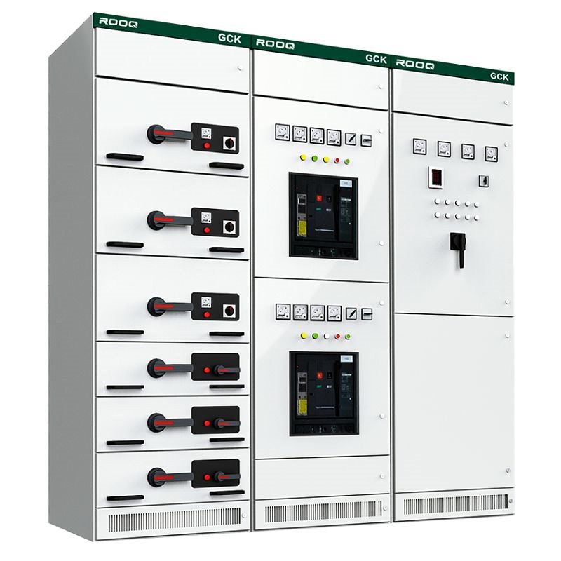
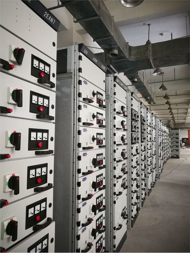
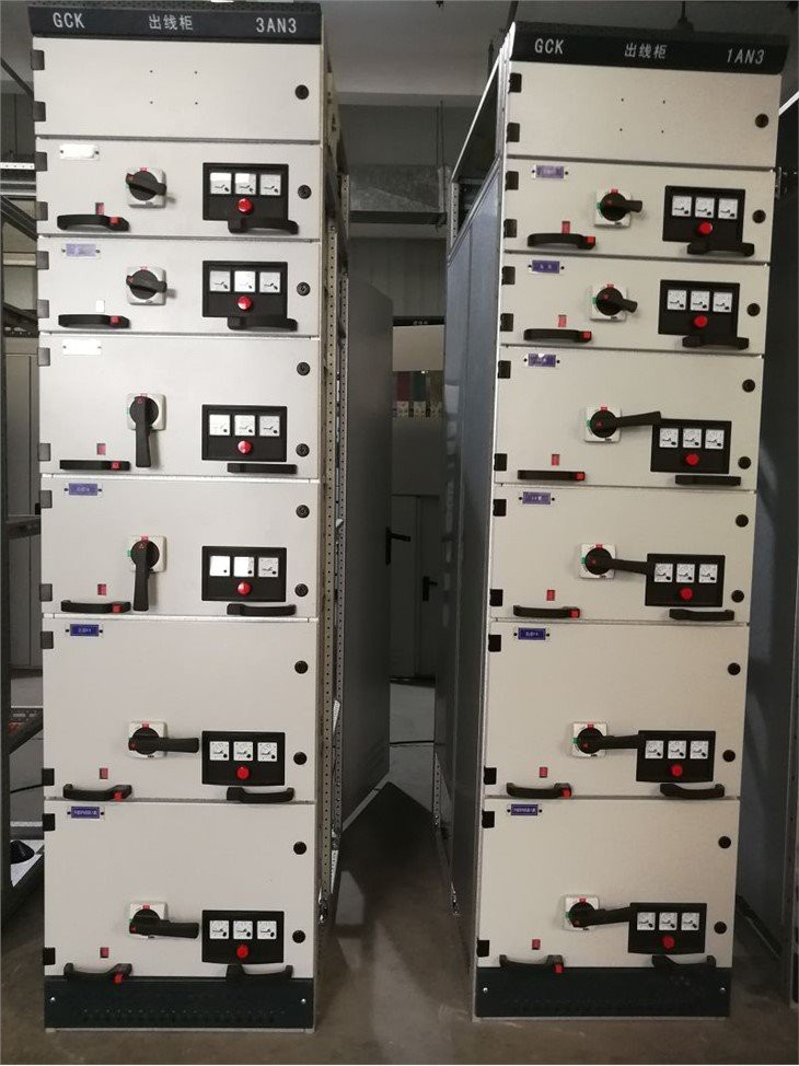
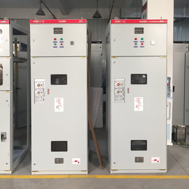
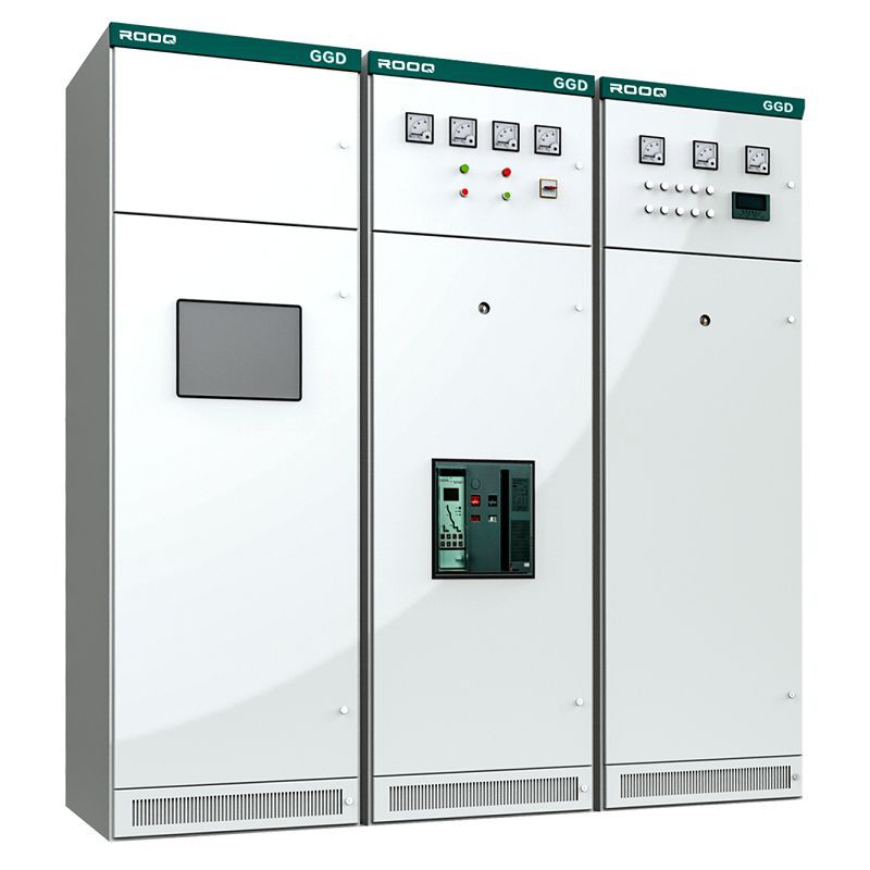
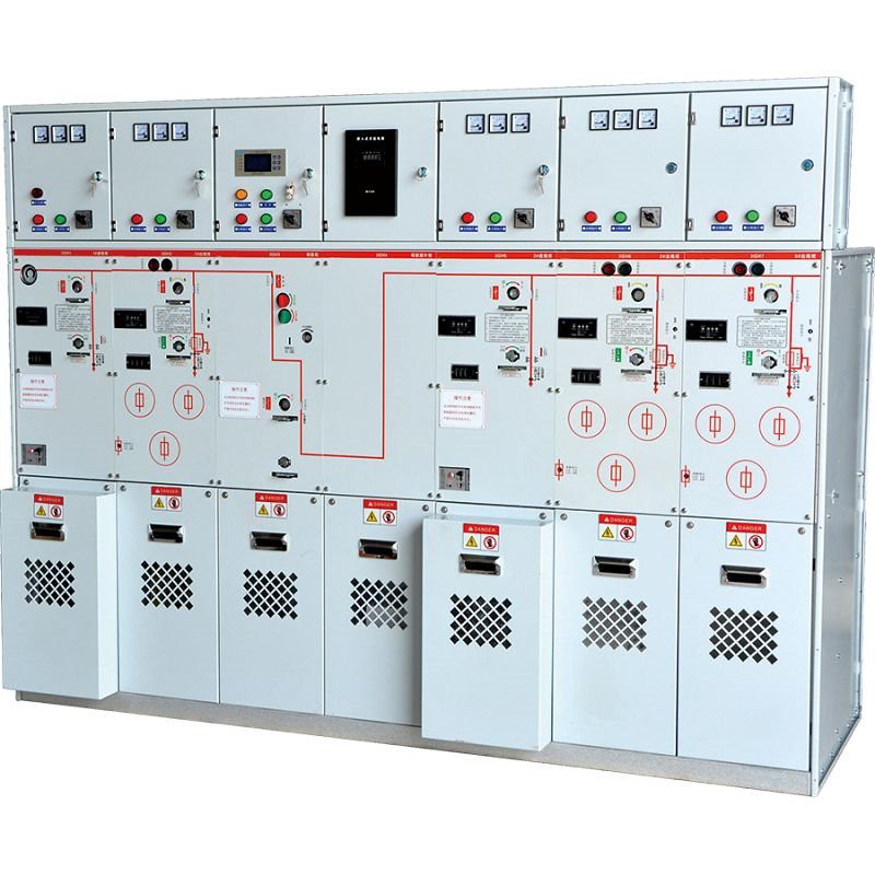
GCK WITHDRAWABLE SWITCHGEAR CABINET
Outline
GCK series low voltage withdrawable distribution switchgear is an assembled advanced distribution device, which is suitable for three-phase four wire or three-phase five wire systems with AC 50Hz and rated working voltage of 380V and below. It is used for power conversion, distribution and centralized motor control of power system distribution equipment in power center (PC) and control center (MCC), It can also form an automatic power supply and distribution control system with program controller and microprocessor.
Structure instruction
The assembled cabinet has its framework made of C profiles. The top is wide-open and the horizontal busbar is placed at the top with the cover open or not. A rear door is provided with the outgoing at the rear, facilitating installation and maintenance. The drawer can be operated with or without the door open. When the door is open the drawer is employed with trigger two-position or three-position operation mechanism and screwed-type feeding mechanism; when the door is not open, the drawer is employed with CXJG type operation mechanism. The primary plug-in is of new type without valve, ensuring more dependability. The rated current of unit loop is up to 600A and I/2 unit drawer can reach maximum current of 100A. The protection degree of the enclosure is IP3X-4X.
Executive standard
IEC 60439-1 Low voltage switchgear and control-gear assemblies
Part 1:Type test and partial type test assemblies
GB 7251.1 Low voltage switchgear and controlgear assemblies
Part 1: type test and partial type test assemblies
ZBK 3600 Low voltage withdrawable switchgear
Service Environment
1. The ambient air temperature shall not exceed + 40 ℃, and the average temperature within 24h shall not exceed + 35 ℃.
2. The lower limit of ambient air temperature is - 5 ℃.
3. For indoor installation and use, the altitude of the place of use shall not exceed 2000m.
4. The air shall be clean. When the maximum temperature is + 40 ℃, the relative humidity shall not exceed 50%; Higher relative humidity is allowed at lower temperatures. For example, the relative humidity is 90% at + 20 ℃, but considering the change of temperature, moderate condensation may occur occasionally.
5. During installation, the inclination with the vertical plane shall not exceed 5 °.
6. The device is suitable for the transportation and storage process of the following temperatures: - 25 ℃ - + 55 ℃, up to 70 ℃ in a short time (no more than 24h). Under these limit temperatures, the device shall not suffer any irreparable damage, and shall be able to work normally under normal conditions.
7. The device shall be installed where there is no violent vibration and impact, and where the electrical components are not enough to be corroded.
8. If the above service conditions cannot be met, the user shall negotiate with the company.
Measurement
Height × Width×Depth:
2200mm × 600mm×800/1000mm
2200mm× 800mm× 800/1000mm
2200mm ×1000mm×800/1000mm
No | Item | Unit | Technical parameter | |
1 | Rated insulation voltage | V | 660/1000V | |
2 | Rated operating voltage of auxiliary circuit | V | AC 380V /220V | |
3 | Rated Frequency | Hz | 50 | |
4 | Rated operating voltage | Horizontal busbar | A | 630/1000/1600/2000/2500/3000 |
5 | Vertical bus | A | 630/800/1000 | |
6 | Rated short-time withstand current | kA/s | 50/30 30 | |
7 | Rated peak withstand current | kA/s | 63/105 | |
8 | Breaking ability of functional unit (drawer) | kA | 50 | |
9 | Motor capacity range | kW | 0.45-160 | |
10 | Dielectric strength | V/1min | 2500 | |
11 | Enclosure protection Level | IP3X | ||
12 | Electrical Clearance | mm | >10 | |
13 | Creepage Distance | mm | >12.5 | |
14 | Over-voltage Level | - | III/IV | |
